All-wheel drive and four-wheel drive may seem like simple concepts, but in reality, there are dozens of widely different systems out there, and a lot of confusion in marketing material and in “common knowledge.” The dead of winter seems like the perfect time for me to publish this ridiculously deep-dive on the various ways cars can power all four wheels.
As a lifelong enthusiast and prolific Jalopnik commenter (HammerheadFistpunch) specialising in all things off-road, I’ve always wanted to write the story of all-wheel drive (AWD), how it works, and how to use that knowledge to cut through the marketing BS for so many years. I’ve taken a few stabs at it, but never in such excruciating detail. Now, finally, I have something I feel is a mostly complete picture of the subject, and I want to share it with you. So, in the absence of some clever metaphor, let’s get into it.
Categories Of Four-Wheel Drive/All-Wheel Drive Systems
Let’s begin by laying the foundation using the Society of Automotive Engineers technical paper J1952 – All-Wheel Drive Systems Classifications. It’s not the law but it should be, and I’m going to be sticking to it, in part, because it defines AWD as any system that drives all the wheels.
All of those debates about four-wheel drive (4WD) being different from AWD — ignore them. In this piece, I’ll only be using “4WD” in reference to specific AWD system names. J1952 calls everything AWD and categorises systems by how they operate, not by the components they’re made up of. It’s clear and accurate, and I’m all about it.
SAE AWD classifications
- Part-time asynchronous / Synchronous
- Full-time fixed torque / Variable-torque passive / Variable-torque active
- On-demand synchronous variable-torque passive / Active
- On-demand independently powered variable-torque active
If none of these make sense to you, don’t worry. They will.
Part-Time All-Wheel Drive
This is what most people call 4WD, and has two defining characteristics:
- User-selectable.
- No inter-axle differential action.
The first is simple enough. A part-time all-wheel drive system requires the driver to do something to go from two-wheel drive to all-wheel drive: either pull a lever, turn a dial, push a button, or activate a setting to connect the second axle to engine power.
The second bullet point — lack of inter-axle differential action — is more important, as it really defines why part-time is called part-time. In other words, it is why automakers want drivers to use this type of all-wheel drive only *part* of the time, and not on dry pavement.
Why Is It Called ‘Part-Time’?
It all comes down to the fact that to navigate a corner without slipping your tyres, your front wheels need to spin faster than your rear wheels, since the rears are able to take a “shortcut” by cutting off the corner, so to speak. To achieve this difference in speed between front and rear axles requires “differential action,” which a part-time AWD system does not allow. So making a tight turn with a part-time system engaged will stress the drivetrain and slip the wheels. (We’ll get back to this concept in a sec).
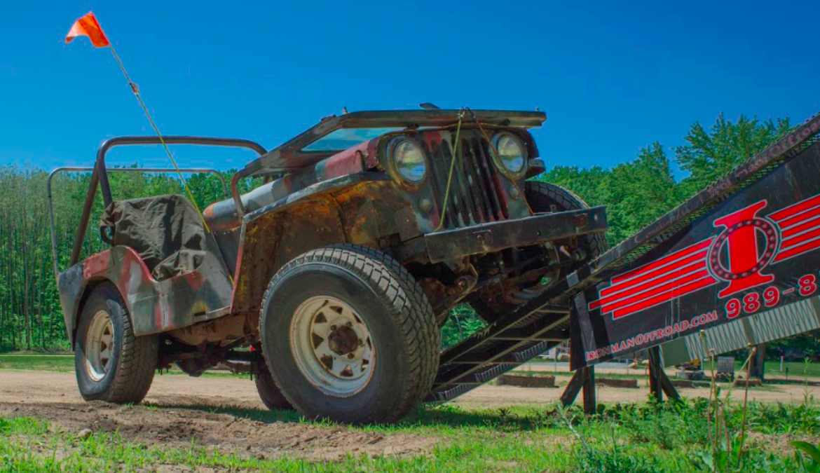
The photo below shows a standard part-time pickup truck-style transfer case as an example (This is a Jeep Wrangler.) There are two subcategories of part-time systems, synchronous and asynchronous, with the former often referred to as “shift on the fly” (in other words, a driver can go from 2WD to AWD without having to stop the vehicle).
Most systems today are synchronous, but most pre-1980 part-time systems require vehicles to be completely halted in order to go into all-wheel drive.
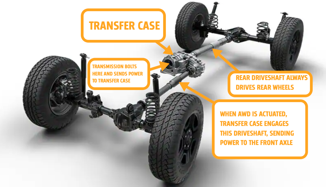
The main part to focus on here is the transfer case, the gearbox after the transmission, and the one charged with splitting power to the two axles.
Take a look at this simplified diagram I drew of the inner workings of a part-time transfer case. The output of the vehicle’s transmission connects to the input shaft of the transfer case (1). A primary axle gets power all the time — usually, that’s the rear axle (2).
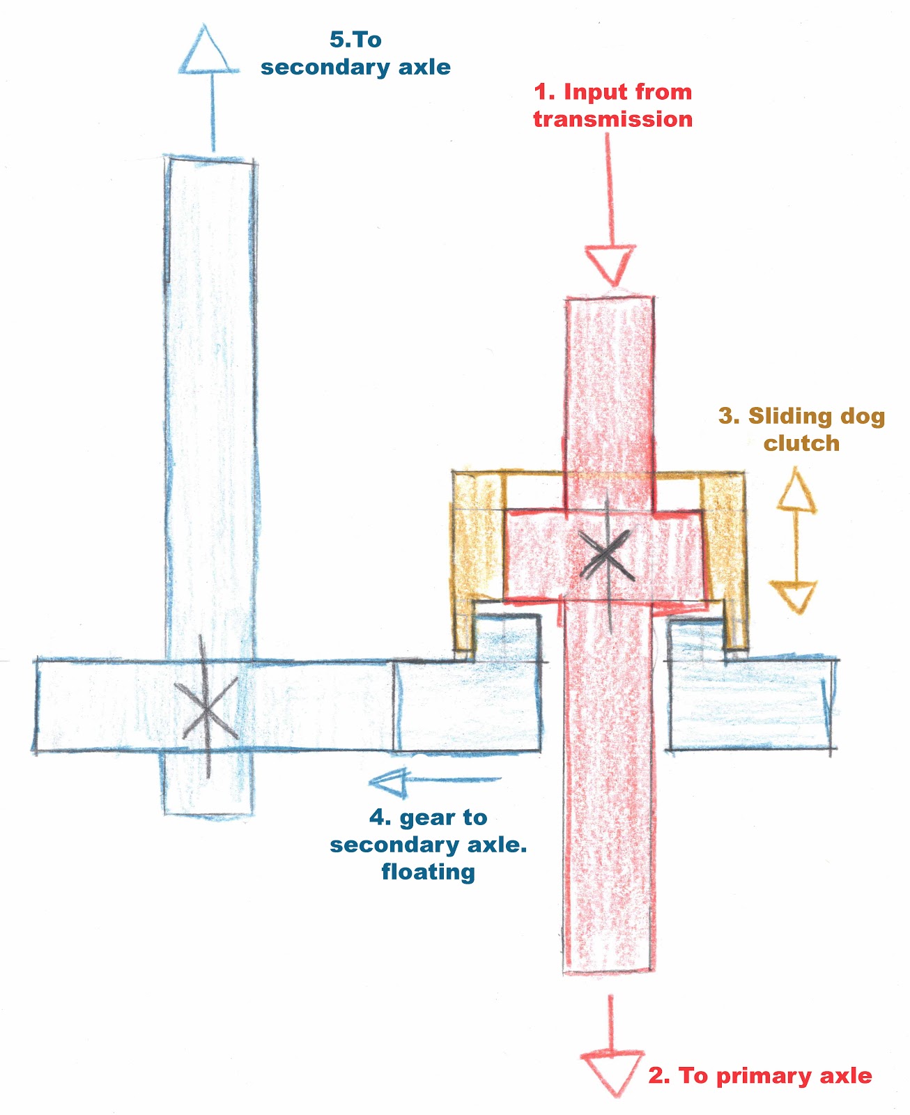
When the secondary (front) axle is needed, the driver engages a dog clutch (locking collar). That device (3) slides in and locks a gear fixed to the input shaft (which is also the output shaft to the primary axle) to a gear that normally floats on that shaft via bearings and is thus not connected to the main shaft.
When moved into position, the dog clutch locks the rotation of this gear (4) with that of the gear on the input shaft (in red). Since 4 meshes with a gear on the output shaft (5), the two parallel shafts will spin together, and torque will be transmitted to the secondary axle. (Note: Sometimes the two shafts are connected via a chain and sprockets instead of gears). When engaged, the front and rear axles are mechanically bound, so they spin at the same rate, offering no differential action.
If you’re curious about what exactly happens when you pull that lever or press that button to engage the shift collar, here’s a look at a collar starring in a hot, steamy roll in a ’80s Toyota training video. Yes, that’s the real music.
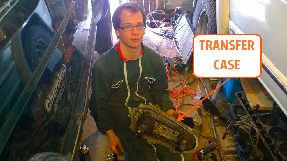
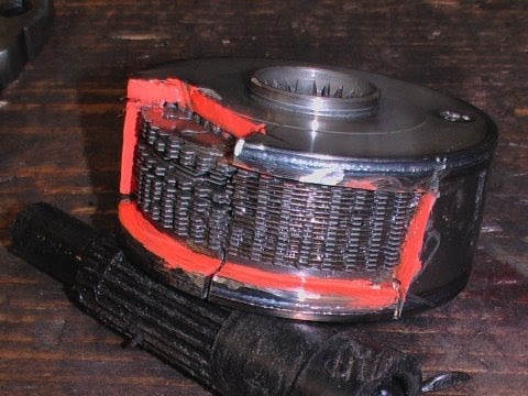
And if you want a look at a silly man showing off the guts of a chain-driven Jeep transfer case, take a look:
What Is Differential Action?
Let’s get back to “differential action.” When a car turns, the inside wheel and outside wheel trace paths of different lengths. In order to keep them in sync, one wheel (the outside) has to turn faster than the inside. An automotive differential is a device that solves this problem, and the effect is called differential action.
Here is a great old video showing the why and how of this on youtube if you want to check it out.
The video above only shows two-wheel drive vehicles. When four or more wheels are driven, you not only have to take into consideration left and right differential action, but also front and back, because as stated before, the rear wheels have a tendency to “cut the corner.”
I wanted to see this for myself so a little while ago I put together a little video using my Land Cruiser as an example.
When engaged in part-time AWD, if you try to turn sharply on a high traction surface, the front axle and rear axle are trying to travel different distances, but spinning at the same angular velocity. For this to physically happen, wheels must slip, which means you end up with driveline binding called windup or “crow hop,” which is bad for your vehicle in high-traction scenarios and potentially dangerous as it makes handling unpredictable.
This is the system on most pickups and off-roaders, from Jeep CJ-5 to Wrangler. They are called part-time for a reason; don’t use part-time on high traction surfaces.
The upside of the lack of speed differential is that a locked system has the ultimate torque bias.
What that means is that all or no torque can go to either axle as needed. For example, if the front axle is on ice, and the rear is on cement, the rear axle will receive all the torque, and the front will receive essentially none because it needs none, or more accurately, it can apply none.
Speed bias and Torque bias are not the same things.
Speed bias is the ability for speed differences to exist between outputs of a device.
Torque bias is the ability for different torque values to exist between outputs of a device while differentiating.
A part-time system has no speed bias, but all the torque bias — no ability to bias speed between the front and rear driveshafts because they act as one, but full ability to bias torque between outputs. It’s often said that power is split 50/50 in a part-time system. The truth is that torque will go where it’s needed, from 100/0 or 0/100. What people are referring to is actually called the nominal torque split.
Nominal torque split is the mechanical relationship between two outputs. We’ll get into this torque split concept a little later on.
Full-Time Four-Wheel Drive
To use AWD on high traction surfaces like dry pavement without driveline binding, you need speed bias, or the ability for the front and rear axles to travel at different rates in a turn. This is done traditionally by replacing the aforementioned locking collar with a 3rd differential called a centre differential. If we look at these expertly drawn scribbles by yours truly we can see how this works, again with a rear-wheel drive-based transfer case as a reference.
Power comes from the transmission into the transfer case (1) and connects a differential carrier attached to spider gears (red). The spider gears push on the side gears with equal force as the case rotates. One side gear is connected to the back axle (2 in yellow) and the other connected to the front through gears or a chain to a parallel shaft (3 in blue). A centre differential works like any other differential, just turned sideways and instead of side-to-side differential action, it’s dealing with front-to-back.
Full-Time Variable Torque Passive
An open centre differential full-time AWD system as shown in the sketch above has a 50:50 nominal torque split, or 1:1 if you prefer, meaning both axles receive the same torque from a mechanical perspective. Remember that nominal torque split is not how much torque can go to either output, but the mechanical relationship between the two sides. Because the spider gears and side gears have the same gear ratio, the amount of nominal torque available to each output is equal.
Open differentials always split torque 50:50. It sounds counter-intuitive since we’ve all seen the “one-tyre fire” single wheel burnout or have been stuck in the snow with one tyre spinning and the other doing jack squat. How can that happen if they are splitting the power 50:50?
Open Diffs Can Not Bias Torque (I.e Each output gets the same torque)
Newton’s 3rd law states that any action has an equal and opposite reaction. That is, the force pushing against, and the force pushing back in a system is balanced. For cars, that means that any force delivered to the road by the tyres must have an equal force from the road pushing back on the tyres. This resistive force is a function of the friction between tyre and road surface, which depends on the weight on that tyre. This concept is called traction.
We often talk about torque as what the engine produces. In order to understand traction, you can’t look at this potential torque but instead, look at the actual or available torque.
We’ll use a two-wheel drive car with one driven wheel on pavement and the other on snow as an example. Imagine your open differential, two-wheel drive vehicle makes a maximum of 203 Nm of torque and has a single 1:1 gear ratio, for simplicity. For the sake of argument, let’s say that traction between tyre and snow is 40 nM of available torque. That is, the tyre will slip and lose traction when more than 40 nM of input torque is applied as that is all the snow/tyre interface can push back with. Let also say that 88 nM is what is required to move the car.
When you floor it and call on all 203 nM of potential engine torque, how much torque is actually applied to moving the car? 81 nM. This is still true if your car made 2711 Nm instead of 200. So why 80 and not 40? Well, you’ll remember that open differentials always split torque 50:50, or 1:1. This is a function of the side gears being the same size and gear ratio, effectively identical “levers” to transmit torque. What one side can apply the other can too. In this scenario, the snow side will quickly exceed 40 Nm and spin while the other stays put. Note that both axles are getting 40 Nm each, for a total of 81 Nm. The stationary wheel on the pavement still gets 40 Nm, but it’s not spinning because the total applied torque is still less than the required, so the car stays put and one tyre appears to get no drive.
This example shows the 1:1 relationship of output torques, called the torque bias ratio or TBR. A 1:1 differential, like an open differential, cannot bias torque. That is to say that an open differential cannot have two different output torques while differentiating. On an AWD vehicle, this means the front and rear axles will always send equal amounts of torque, the amount which can be applied to at a single axle.
Limited Slip Diffs
Locked systems have total torque bias while open diffs have no torque bias. Somewhere in the middle is a partial or limited locked state, more commonly called limited slip.
Limited slip differentials work by varying the degree of connection between the two outputs. In the case of a locked system, they are completely connected. In a limited-slip, they are connected in a limited way. This is accomplished by adding resistance or friction between the outputs. Total friction being locked, no friction being open.
An Eaton Posi (short for Positraction, which you may recall from My Cousin Vinny), shown above, is a classic example. It uses spring force to push side gears against friction discs against the case, to increase friction between the two outputs. Friction can be added internally to the differential (called a limited-slip differential) or by adding friction in parallel, or “over” the differential (i.e. you append an open differential with some kind of friction device separate from the diff).
The Viscous Coupling
One once-common way to do the latter was to add a viscous coupler over the open differential. A viscous coupler works a little like an automatic transmission torque converter in that the fluid is the transfer medium. In other words, an input “pushes” fluid to spin an output.
The Toyota training video above, which gets really exciting at around two minutes, clears it up substantially.
A viscous coupler has discs on the input shaft that spin freely, and discs that are fixed to the case. In the middle is a highly viscous (i.e. thick) fluid. If there is a significant speed difference between the input and the output (in other words, between the speeds of the front and rear driveshafts — this would indicate slip), the thick fluid acting against the discs resists the speed difference in an attempt to re-synchronise the output speeds. This ultimately allows the two outputs to behave like a somewhat locked system, sending power to the secondary axle until the slipping axle gains traction.
My current daily driver Land Cruiser 80 series uses exactly this setup. Come to think of it, so did my vehicle before, a 2005 Subaru Forester XT 5-speed. Subaru calls this continuous AWD, and my Toyota calls it full-time 4WD, but it’s the same in either case. To see how adding a viscous coupler over an open differential works, we’ll use the cutaway of the Subaru five-speed manual transmission I had in my Forester.
In this diagram, we can see how the viscous coupling fits in. Power goes through the transmission (you can see the gears labelled first through fifth) to the countershaft (11) which turns the centre differential case (10). The case turns the internal spider gears which act on the side gears. One side gear goes to the front pinion driving the front differential by way a shaft inside the hollow countershaft (14) and the other side gear goes to the back via a transfer gear set (6 and 8). The Viscous coupler case (9) is attached to the centre differential case on one side, and one of the side gears is connected to the rotating part of the VC. This arrangement means that the centre differential case and one of its outputs, in this case, the rear output, are trying to stay synchronised through the resistance of the coupler.
If the front is spinning faster than the rear, the rear side gear spins slower than the case, and the viscous coupler attempts to slow down the front and speed up the rear, sending additional torque to the rear. The same goes for if the rear is spinning faster than the front. This arrangement still allows for speed bias to happen and corners to be safely navigated in AWD, as the speed difference in a turn is very small and the locking effect is still limited.
While Subaru still makes and sells this system, manufacturers have mostly moved past it and onto other systems because of better control and durability. Viscous couplers are often destroyed when abused by going into a temporary locking mode called, and I’m not making this up, “hump mode.” Going into hump mode damages discs and causes deformation and cracks in the case resulting in unit failure. So hump responsibly, no one wants unit failure.
In most cases, you’ll know you done screwed up if your viscous coupling equipped full-time AWD, Jeep Quadra-drive for example, is acting a lot more like part-time by scrubbing, binding, and hopping in turns.
Internal Limited Slip Diffs
Moving beyond viscous couplings, are internal limited-slip differentials. One of the first is still one of the best. In 1949, a man named Vernon Gleasman patented his novel Torsen differential, a portmanteau of TORque and SENsing. These are the centre differentials that made Audi Quattro famous and what makes mine and Rory’s Lexus GX470 so capable in the snow.
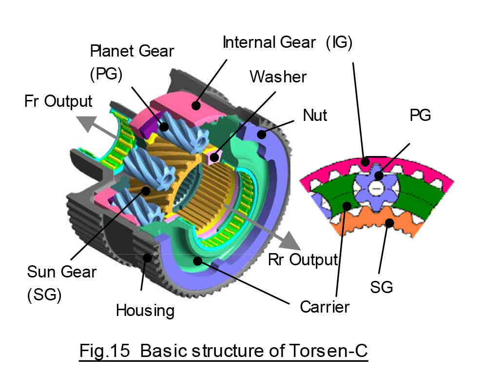
The above diagram is the Torsen type-C from my Lexus, Type-C for “centre”. Geared as a planetary gearset, it allows for speed bias and torque bias in a single unit — so it can offer differential action, but also not necessarily give the same torque to each axle, meaning if one axle can apply less torque than the other, torque can be sent across the differential to re-sync them.
This particular Torsen features a nominal torque-split different than 50:50, with one output having more gear teeth than the other output, such that the fixed nominal torque split is now rear-biased 40:60 front to rear. This doesn’t change the output speeds, just the relative nominal torque split. i.e. different length levers, but the same rotational speed.
As a limited-slip device, it can send torque across the differential to different outputs. The GX470 can go from 29:71 front to rear to 53:47 front to rear depending on road conditions and traction needs. This range is its torque distribution ratio, from 53 % to the front to 71 % to the rear. So long as the front axle never needs more than 53% of the torque or the rear more than 71% then slip is managed.
The amount of torque that can be biased by a device is known as the Torque Bias Ratio [TBR] as mentioned above, with open differentials being 1:1. A 3:1 TBR limited slip can bias 3 times the available torque for one output compared to the other.
Here is an example of what that means.
We’ll use the same example as before, with an FWD car stuck with one tyre in the snow and the other on the pavement. You’re getting tired of getting stuck, so you installed a limited-slip differential with a 3:1 TBR. The tyre in the snow still can only apply 40 Nm but now it can bias torque to the other side to the tune of three times what one side can get. The tyre in the snow gets 14 kg-ft and the tyre on the pavement gets 120 Nm (3 x 30), for a total of 162 Nm, which is more than the required 88 Nm to get you moving.
Another way to talk about limited-slip is called the locking effect. Locking effect is the per cent “locked” the device can be. 100% locking effect is locked, 0% locking effect is open. Locking effect is derived as (1-TBR)/(1+TBR) x 100, or the relationship between the difference in outputs compared to total output, expressed as a per cent. A 3:1 TBR differential can be said to be 50% locked (2/4 = .5 x 100 = 50%). What that looks like in a centre differential with a nominal 50:50 torque-split would be a torque distribution ratio that ranged from 15:75 front to rear to 75:15 front to rear with managing slip. 25% above the nominal and 25% below the nominal.
TBR, as it relates to locking effect, is a diminishing return. A 6:1 TBR is not twice as good as a 3:1 TBR, for example. Doing the maths shows us why. 5/7 x 100 = 71.5% locked. If it were linear a 6:1 TBR would be 100% locked, because a 3:1 is 50% locked. Because of this relationship, as locking effect approaches 100%, the TBR approaches infinity. So a locked system is said to have an infinite:1 torque bias ratio. The SAE calls this an indeterminate bias ratio and why locked systems have total torque bias. 0:100 or 100:0
If you’ve tried off-roading with an LSD, or are just good at maths, you’ve probably already seen the limits of an LSD. If you have a wheel in the air, then zero units available torque from the resistance of the air times a 3, 4, 12, or 20:1 TBR will still result in o torque to the high traction wheel.
Take a look at the 4Runner above with the exact Torsen centre differential we’ve been talking about, trying to move with the front wheels on solid footing with the rears on ice. The limited available torque the ice can support multiplied by a 1.86:1 TBR is still not enough to move the vehicle forward.
To solve this, this centre differential can be locked, bypassing the differential. Most full-time AWD off-roaders have locking features for their centre differentials for this reason. When locked, a full-time system acts as a part-time system. Not including a locking centre differential, either mechanically or through clutches, on an off-road vehicle doesn’t make a lot of sense. Looking your direction Land Rover.
Full-Time Variable Torque Active
So far, all the systems we’ve talked about have been “passive” in that they did not utilise external feedback control to change torque distribution between axles. With an active system, instead of adding a passive coupler to a centre differential, what if you added an active one, like a computer-controlled clutch pack?
These work just like a viscous coupler, with discs on the input and output, but instead of using fluid to transmit torque, they use the friction of the clutch plates.
Using feedback from sensors like ABS wheel speed sensors, computers control the clutches electro-mechanically or electro-hydraulically. When the computer commands more torque, accumulated hydraulic pressure is valved to a piston, then to the plates to apply the pressure. This can also be done with electromagnets and ball ramps, but most manufacturers use hydraulics for its control, speed, and power.
One example that uses hydraulic control is Subaru’s DCCD, or Driver Controlled Centre Differential on STI models. Despite the name, DCCD isn’t entirely dependent on driver input, but it does allow the driver to select tunes of the automated system or to select preload levels manually.
The system uses a Torsen centre differential with a 41:59 front to rear nominal torque-split. Because the Torsen differential is a limited-slip, it has the ability to change the torque distribution ratio around that nominal split. Assuming it’s the same TBR as the one in my GX, we can guess that with the DCCD in fully open mode, an STI can bias from 24:76 to 57:43 front to rear.
Where the DCCD comes into play is when you need additional bias. As commanded by the computer or user, the clutches apply additional friction to the centre differential increasing the TBR up to and including fully locked. In a locked state you move to part-time AWD where speed bias is entirely gone and torque bias is full.
Fully locked allows you to realise maximum traction and torque bias potential, and stabilizes the car in loose conditions, but it makes the vehicle resistant to turning and has all the drawbacks of part-time AWD. Auto + mode increases the amount of lockup pressure based on sensor feedback, auto – decreases it. Manually controlling it takes the computer out of the equation and forces the clutches to engage at predetermined levels up to fully locked.
The beauty of active systems is the ability for external sensors and programming to adapt to situations automatically, never leaving a driver without the traction of full-time AWD, and increasing potential traction and driving characteristics on the fly.
On-Demand Synchronous Variable Torque Passive
What a mouthful; let’s dissect.
- On-demand – Meaning torque is sent to the secondary axle as needed, and not by default.
- Synchronous – This means that it can be engaged while in motion.
- Variable Torque – When engaged the torque sent to the secondary axle can vary.
- Passive – Doesn’t rely on external feedback systems.
One such system was VW T3/T4 Syncro vans, seen in action above, which relied solely on a viscous coupler. We talked about viscous couplers above as a limited-slip adder for open differentials. Originally these devices were conceived as a standalone coupler to add AWD cheaply and easily, without a centre diff, in a way that would require no user input and be economical to make and run.
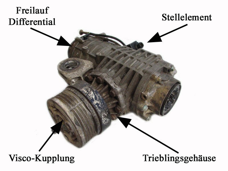
This is the front differential unit of a T4 Syncro. You can see the “Visco-Kupplung” before the differential housing. The pinion, ring gear, and open front differential all come after the coupling in the housing. In normal operation, the front axle and rear axle are in sync and there is no torque being sent through the coupler to the front axle. With sufficient speed difference between the axles’ angular velocities, the viscous fluid causes a binding action in the coupler, and torque is sent through the coupling to engage the secondary axle. The T4 also had an overrun clutch on this secondary axle so as not to bind up during ABS and deceleration, basically freewheeling the coupling, the “Freilauf Differential” labelled above.
This on-demand secondary axle engagement is the forerunner of today’s modern systems.
On-Demand Synchronous Variable Torque Active
This brings us up to today where the lion’s share of modern AWD systems live. As you can guess, on-demand synchronous variable torque active is just like the passive system mentioned above, but with an external feedback system that actively manages secondary axle engagement. While there are many ways to do this, they all generally take on the same basic forms. Replace the viscous coupler in the VW example above with computer-controlled clutches and you have the basic idea.
These systems and technologies, while most commonly found on crossovers, aren’t exclusive to them. They are in fuel-efficient front-wheel drive-based vehicles will less than 100 horsepower and also in rear-wheel drive-based 520+ KW track cars and trucks.
So to make it easier to understand these modern all-wheel drive systems, let’s break them down into two basic categories.
- Transfer Case-based
- PTU/RDM or “Hang-On” systems
On-Demand Active AWD — Transfer Case-Based
An on-demand transfer case is very similar in concept to a full-time or even part-time transfer case, only instead of having a centre differential or a locking collar, you have a coupling, usually clutch-based. One version of this setup is the Borg-Warner Torque On Demand transfer case. Here’s a look at how the system works:
Under normal operation, little to no current is applied to an electromechanical clutch pack that applies pressure to the clutches to engage the front axle. Based on sensor input, computers can command more torque, at which point more current is applied and the clutch engages further, bringing the front axle to bear gradually all the way up to fully locked.
This technology has been around since the 90’s in vehicles like the Chevy Trailblazer and Isuzu VehiCROSS but honestly wasn’t very good in everyday use, being a little clunky and sharp. Active transfer cases have only really come into their own lately with advancements in material science and processing power allowing for far more seamless operation. You may know these systems by the name “4H Auto” or “4Auto”.
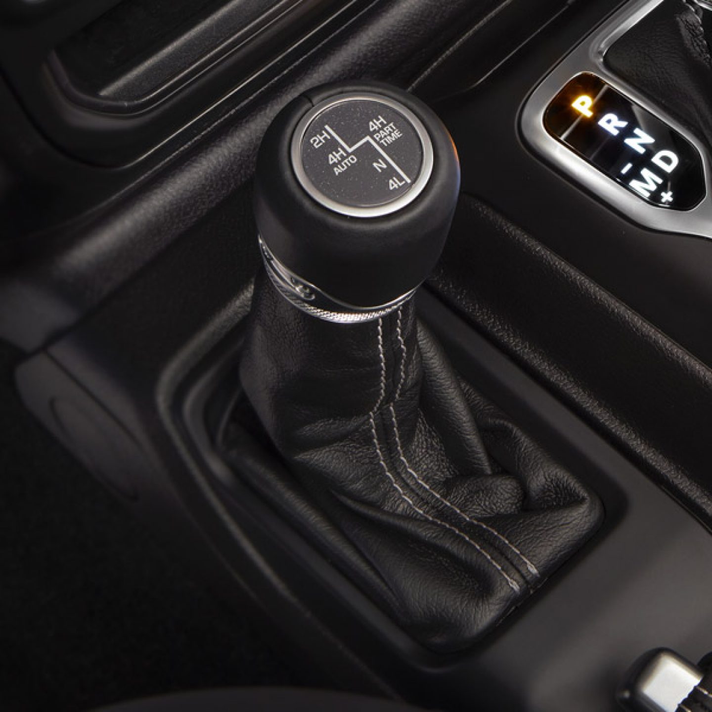
Active transfer cases are usually found in trucks that would normally have a“4WD” option, but require the additional luxury of automatic operation or where AWD traction is needed for everyday or performance use. GM uses these systems in some of its light and heavy-duty trucks, Jeep has it as an option on all trims of the 2021 wrangler, and it can even be found in dinosaurs – The Ram TRX and Ford Raptor.
The advantages are numerous.
- Finely controlled torque biasing potential
- Potential for dramatically reduced driveline losses
- Tune-ability
- Locking operation
Many of these systems fall on the line between full-time AWD and on-demand AWD by having a preset secondary axle torque value programmed in. An example would be the RAM TRX, which never has less than 30% of torque sent to the front axle.
Chip Fairbanks, an engineer who worked on various AWD systems for a major supplier, explained how this worked to me using the 1st Generation Jeep Grand Cherokee SRT8 he worked on as an example.
“More modern systems, or at least 10 year old modern, are proactive and try to have some amount of torque already available in the clutch at all times. In a way, the software is trying to use the clutch to mimic a mechanical differential. Allowing slip across the clutch when turning but having it partially closed based on other conditions. We would set a basic torque spit, say 40/60 on a Jeep Grand Cherokee. The software would look at available engine torque and multiply that by the current gear ratio then set the clutch to have a capacity of 40% of that number.
So for simplicity, say the engine was outputting 1000 Nm of torque and in a 1:1 gear the clutch would engage to what would be equivalent to 400 Nm of torque. Just because the clutch was closed to this amount wouldn’t mean it would be transferred to the front axle. But if the rear wheels happened to lose grip, the clutch could at that moment transfer 400 Nm of torque. At the time we were calculating this ideal torque valve every 10 milliseconds, and it varied based on wheel slip, steering angle, and a bunch of other signals. This was the “base” mode, turn the switch to sport mode and the basic split would change to 30/70 to liven up the rear end a bit. Go to Sand mode and the basic setting would go to 50/50 for better traction. So with an active clutch anything is possible, it really comes down to the tuning of the software.”
Mostly RWD, slightly RWD, or fully locked, with decisions made every 1/100th of a second — that’s something I think we can all be excited about.
Want to see what that looks like? Of course, you do! Chip sent me the video above taken by a colleague during the development of the SRT8. Watch the machine blast around a go-kart track with engineering overlays — it’s worth checking out!
Notice how on hard braking events the program (green line) says to reduce coupling pressure (white line), and as soon as acceleration is requested the coupling pressure comes on fast and strong. Very cool.
On-Demand Active AWD — PTU/RDM or “Hang On”
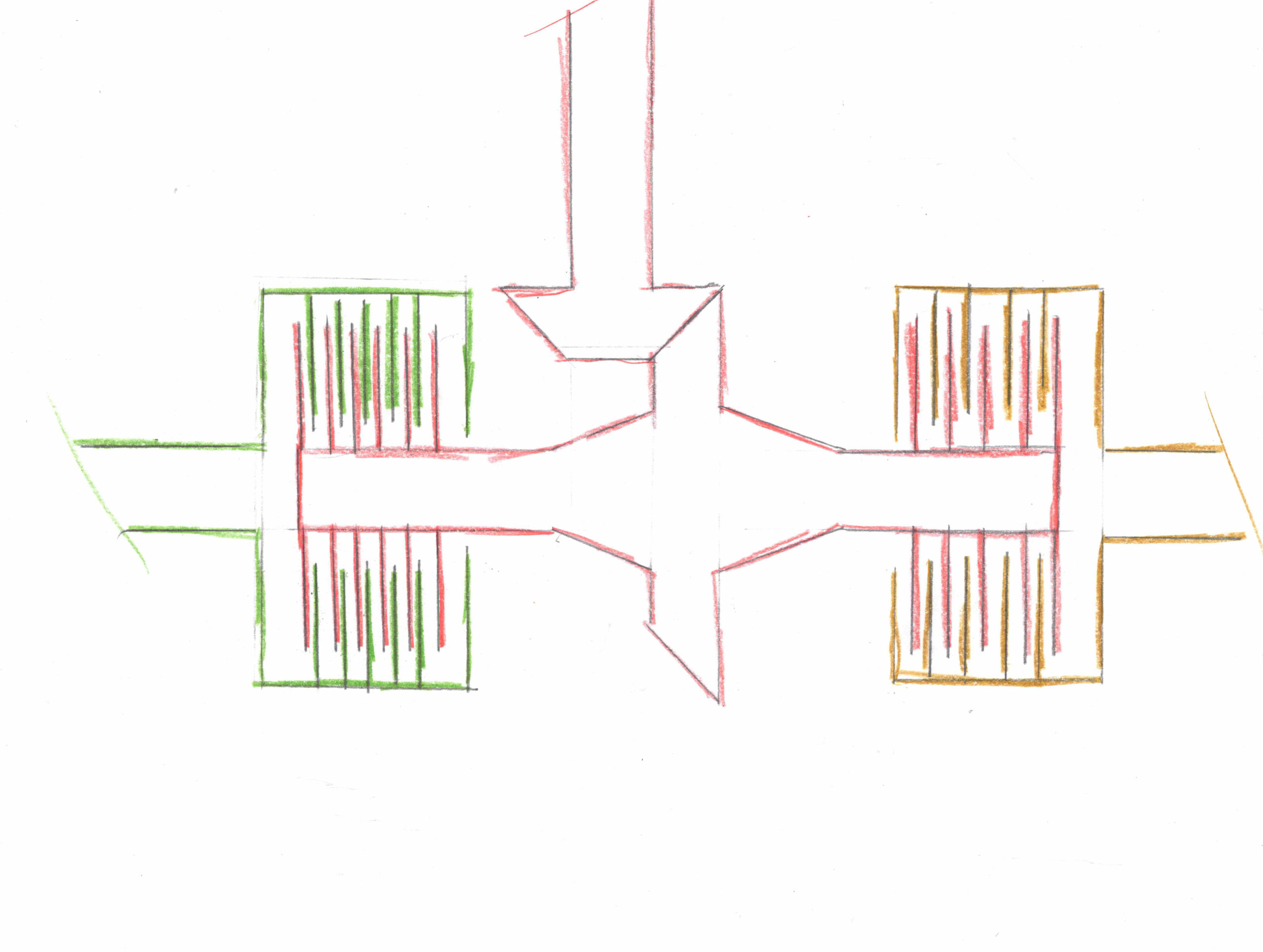
A PTU or Power Transfer Unit is basically just a transfer case turned sideways, with one output headed 90 degrees off. As such, the principles are, more or less the same with a few components missing and moved to other areas.
In most modern PTU’s, torque is split like a permanently engaged part-time transfer case. Power comes from the differential case inside the transaxle, which has already had its final drive reduction applied, into the PTU (1). The Front differential in the transaxle works exactly the same as it would without AWD, sending torque to the left and right side axles from the side gears, left (orange) and right (yellow) respectively. The PTU case is bolted to the transaxle case. Inside there is a hallow shaft connecting the front differential case to the transfer gears allowing the front right driveshaft to pass through it (3). The transfer gears, which turn the power 90 degrees, are attached directly to the front differential case and its final drive reduction.
Speeding Up The Rear Driveshaft
The transfer gears also have another function of “speeding up” the rear output (i.e. rear driveshaft) after the front differential reduction. This is done, presumably, because a 1:1 ratio ring and pinion isn’t practical so the rear-drive is sped up, only to go into a reduction by the same amount (as the transfer gear ratio) at the rear ring and pinion in the RDM for a net-zero change in speed. Remember that the rear output of a PTU is connected directly to the front differential which has already had its final drive ratio applied, so a reduction at the RDM requires an RPM increase post-PTU. (Note: The wheels actually speed up the driveshaft so that its rotating at the same angular velocity as the PTU output, allowing for seamless engagement).
This configuration allows AWD to be added to any FWD transaxle with minor modifications, making them very easy to “hang-on.”
Examples of this system are found on…pretty much anything with a transverse layout and AWD option today.
The two differentiating factors of PTUs compared to transfer cases are:
- Secondary axle power is turned 90 degrees
- Final drive reduction happens in the transaxle and not in the front and rear differentials.
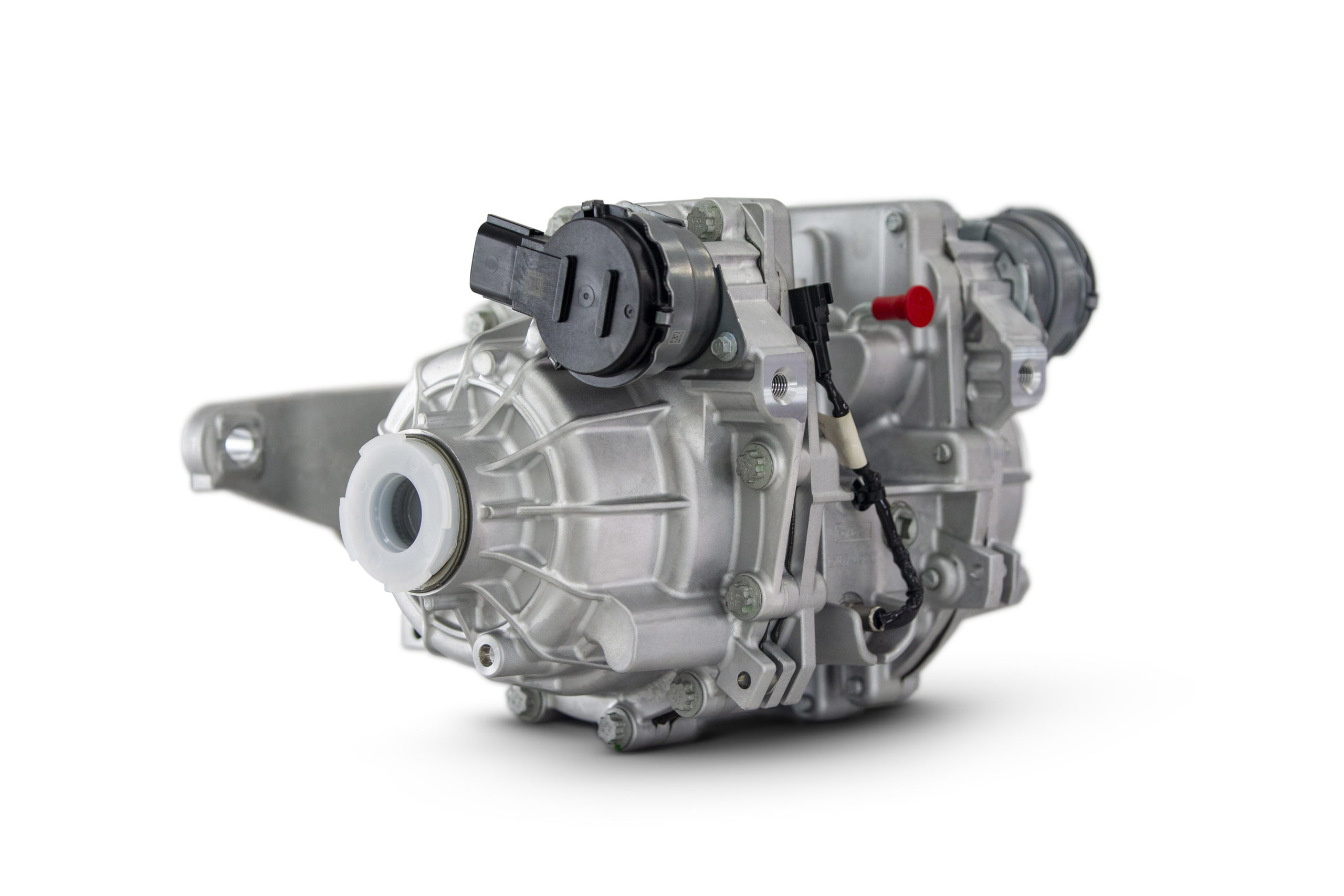
Above is a cutaway of a Toyota PTU unit. You can see where it bolts to the transaxle on the left, where the right drive passes through the middle of the transfer gear in the centre, and the overdriving of the rear output on the spool. The spool replaces a centre differential with a solid chunk on metal. In most cases, this is how the PTU is configured, which is why it acts like a permanently engaged part-time system, at least to this point.
Just like on-demand active transfer cases, the speed and torque biasing happen in a clutch-based coupling instead of a differential, which allows for some speed bias while also offering torque bias capability as needed. Unlike an active transfer case, where the coupling is in the same case where the torque split happens, this coupling is found at the base of the secondary axle housing at the end of the drive shaft. The coupling, together with the rear axle, is called the rear-drive module, or RDM. A hang-on system like this consists of a PTU and RDM combination working in tandem.
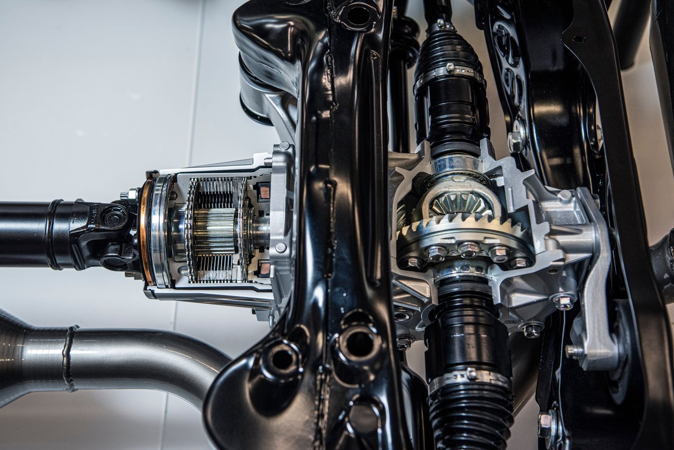
Above is the RDM from the Toyota GR Yaris which shows an up-sized coupling and the rear differential for the RDM.
Pros:
- Fewer parts needed
- Easy adaptation of current drive systems
- Separation of transfer case and centre coupling functions
- No user intervention needed
- Minimal drag from the secondary axle when disengaged
- Torque bias ratios of greater than 1:1 possible
Cons:
- Limited or no nominal torque split.
- External feedback required for operation requiring electronic components and programming
- Some possibly delay in commanded torque and actual torque
Originally these systems were mostly reactive, looking at wheel speed sensor data to see slip, and engaging the clutch post-facto. Many people refer to these systems as “slip & grip,” and that description used to be pretty accurate. Systems today are far more proactive and look at a variety of sensor inputs like steering wheel angle, throttle position, accelerometers, even rain sensors for the wipers so they can engage the secondary axle before slip occurs.
Some systems have a set preload on the clutches either mechanically through springs or in the programming, to ensure that some torque is always at the secondary axle. Most manufacturers prefer to disengage the secondary coupling completely for fuel savings when not needed such as driving on the freeway. Because the coupling happens at the RDM, this leaves the driveshaft still spinning and some systems add a dog clutch at the PTU to disengage the rear driveshaft and further reduce losses, though at some expense to engagement time. In this case, the PTU is now like a part-time AWD system that isn’t permanently engaged.
Note: some older PTU-based systems had centre differentials and they would technically be classified as full-time AWD, and not as on-demand. For example, 1st and 2nd generation RAV4 with manual transmission or other similar era Toyota All-Trac systems. (Celica, etc)
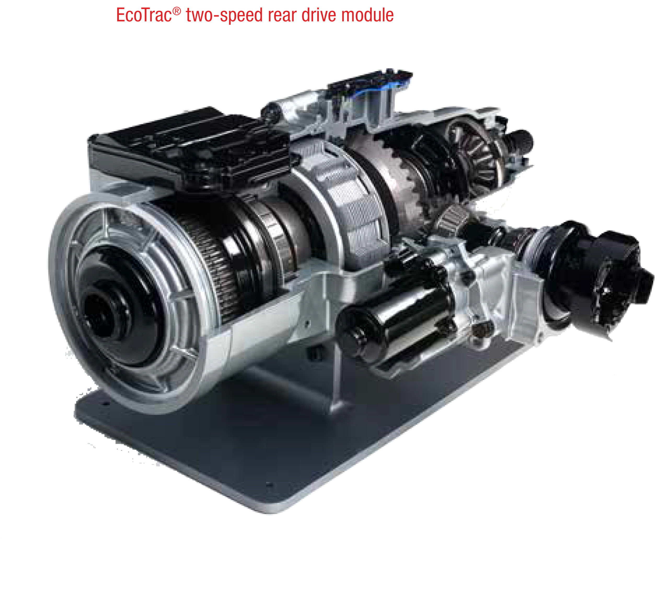
Hang-on systems add a minimum of weight (between roughly 80 and 59 kg) and drag, and make the decision between AWD and fuel economy much less of an issue for manufactures and consumers. An example of a fully decoupling system is the AAM EcoTrac system, shown below in operation.
The Jeep Cherokee Has A Separate Low-Range Gear For Each Axle
The EcoTrac is also an interesting anomaly in the PTU/RDM world. It comes in regular (EcoTrac) and two-speed (EcoTrac II/Lock) flavours and remains the only 2 speed PTU/RDM option in production today as found in the Jeep Cherokee with the ActiveDrive II or ActiveDrive Lock option.
The EcoTrac II PTU (shown above) has a planetary gear reducer for the front axle after the final drive reduction from the front differential case. This reducer works only on the front axle only. The rear driveshaft, connected to the front differential and final drive reduction, still spins at “high range” speeds and doesn’t know that the front axle is in low range. When drive gets to the RDM, it needs to be reduced again by another planetary reducer with the same ratios as the front, after the reduction done by the ring and pinion on the rear differential case.
In effect, the 2-speed EcoTrac II equipped Jeep has 3 planetary transmissions. The 9-speed transaxle, the 2-speed reducer in the PTU that slows down the front wheels in low range, and the 2-speed reducer in the RDM does the same for the rear (shown below). Also unique to the Ecotrac Lock is an RDM rear differential with an actual dog clutch locker. For reference, the centre coupling in the AAM system inline left of the ring gear but its function is exactly the same. The open (locking in the case of ActiveDrive Lock) differential is seen far right.
So why aren’t there more vehicles like the Cherokee with FWD based hang-on systems with robust off-road AWD options? When asked, Fairbanks confirmed my base suspicion.
“Cost, weight, and consumer demand,” he said. As you can see, these components don’t look small or cheap. Still, if you are a manufacturer who wants a hang-on AWD system meant for off-roading, you can most certainly get it and if you are a consumer who wants this feature, you need to demand it for manufacturers to start making it happen.
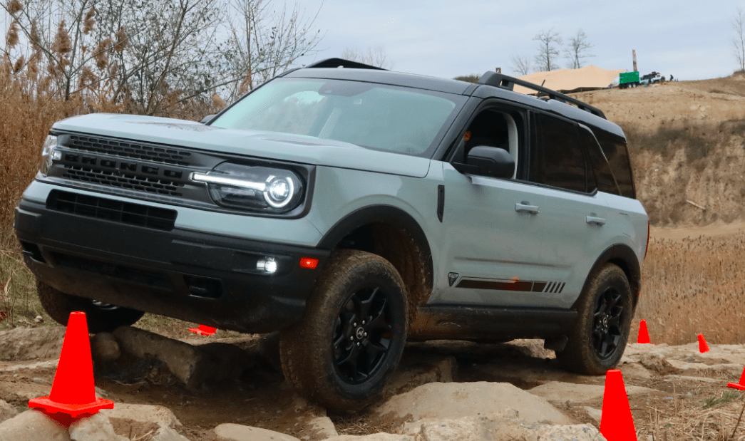
Imagine a RAV4 TRD, or discovery sport or Bronco sport, or any number of off-road-focused crossovers but with a proper low range reduction and actual locking differentials.
In most cases and for most people, the reality is that a centre differential is overkill in normal driving for speed bias as the speed differences between axles while driving on the pavement are relatively small and infrequent, and expensive technology is needed to overcome geared differentials’ inherent disadvantages for torque distribution. With a clutched RDM, a computer can manage the small speed biases by allowing slip in the clutches but can also bias torque relatively easily.
To find out more about these couplings I went to visit car guru, Weber State University Professor of Automotive Technology and YouTube godsend John Kelly.
Big Clutches Can Transfer Lots Of Torque. Small Ones Will Slip
One of the first questions I asked was about the theoretical limit of these couplings. John showed me an Allison 1000 six-speed transmission used in GM HD trucks and heavier vehicles; the gearbox was conveniently torn apart on the bench. He pointed to a tiny cup on the transmission about six inches across and three inches deep. “That,” he said, “is the C1 clutch, and all the engine’s torque in 1st gear goes through that.”
All the torque of their diesel, through that tiny clutch pack…and it works.
Basically, he tells me, it’s about surface area. More plates mean more surface area. More surface area generally means more strength. It doesn’t matter if you build a larger-diameter clutch or stack the clutches, it’s the surface area that matters.
The strength of the couplings then isn’t a technological limitation, but more of a practical limitation; all of these systems are a dance between cost, packaging, capability, and consumer expectations. As automotive science advances, mechanical overkill is being replaced with efficiency in design.
The reality is that today, manufactures would rather a handful of people be slightly let down by the ultimate capability of their system than deal with longevity or drivability issues stemming from abuse or niche scenarios that programmers hadn’t envisioned.
An interesting challenge, according to Chip, is being able to handle shock loads from ABS-based traction control suddenly adding huge resistive torque loads on the coupling. The couplings are sized to handle them, but not for being fully locked at the same time.
These clutches though are very robust within their design limits and can handle slip with relative ease and as John and Chip both confirmed are generally long-lived.
Something else worth considering is that while these systems are carefully tuned for each vehicle, they are generally not being made for the vehicle by the manufacturer, but rather made by suppliers; AAM, GKN, JTEKT, Manga, etc. to name a few. They are called “hang-on” AWD for a reason and making custom systems for each vehicle somewhat defeats the ubiquity advantage of such a setup. This means that while manufacturers can shop around for the system that best suits their needs and request features, the ultimate design constraints are largely out of their hands. In the end, programming, not hardware will likely be the difference between a capable system and a less capable one.
Modern “4WD Lock” Buttons
This brings me to something of a personal sore spot with some on-demand AWD vehicles – buttons that suggest that a centre or rear differential can be locked. A prime example would be the new Bronco Sport Badlands which has what looks like a centre and rear diff lock button. Given that they have no centre differential, or even rear differential (more on that in a minute), what do these actually do?
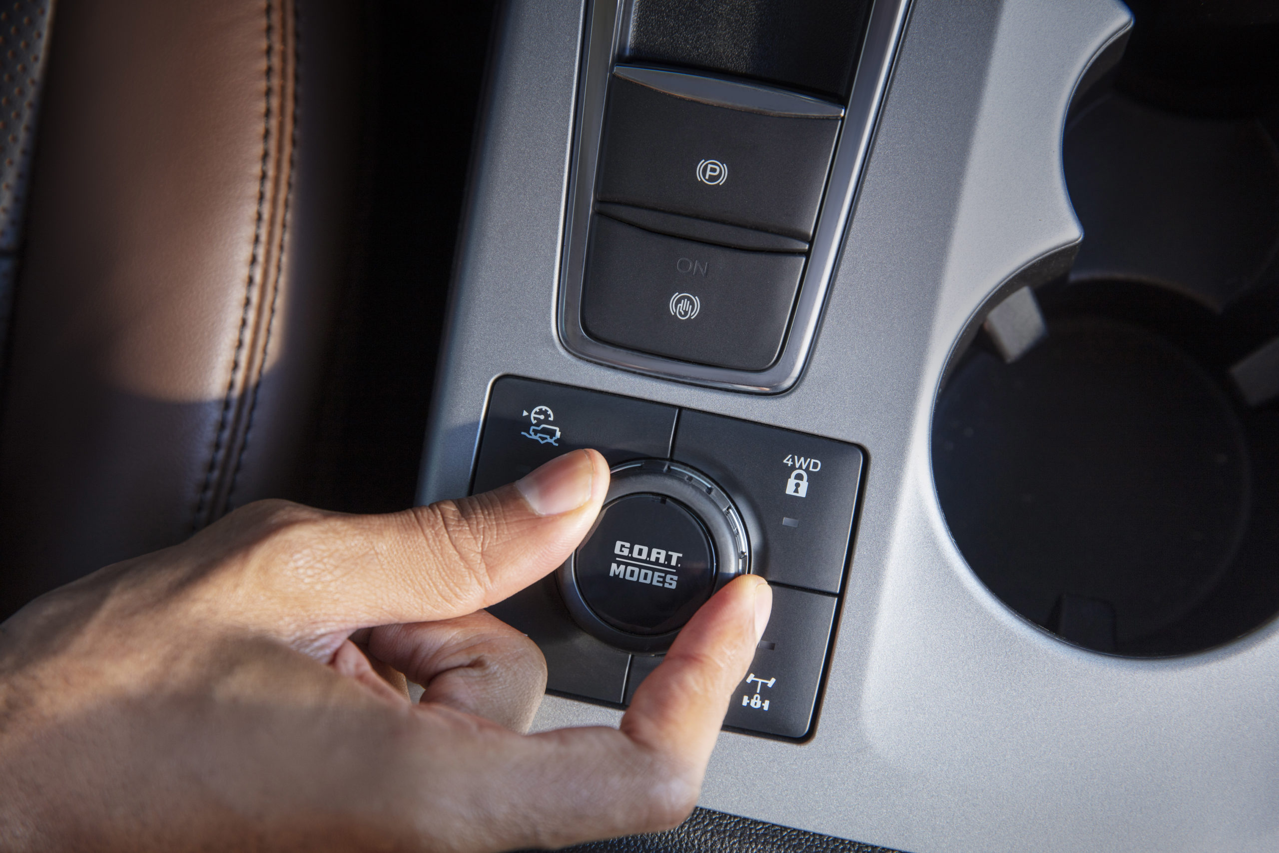
“Most are just little more than a marketing gimmick,” says Chip. “They lock the coupling for a short time, usually only at low speeds. Some stay locked with steering input and others open the coupling [as needed].”
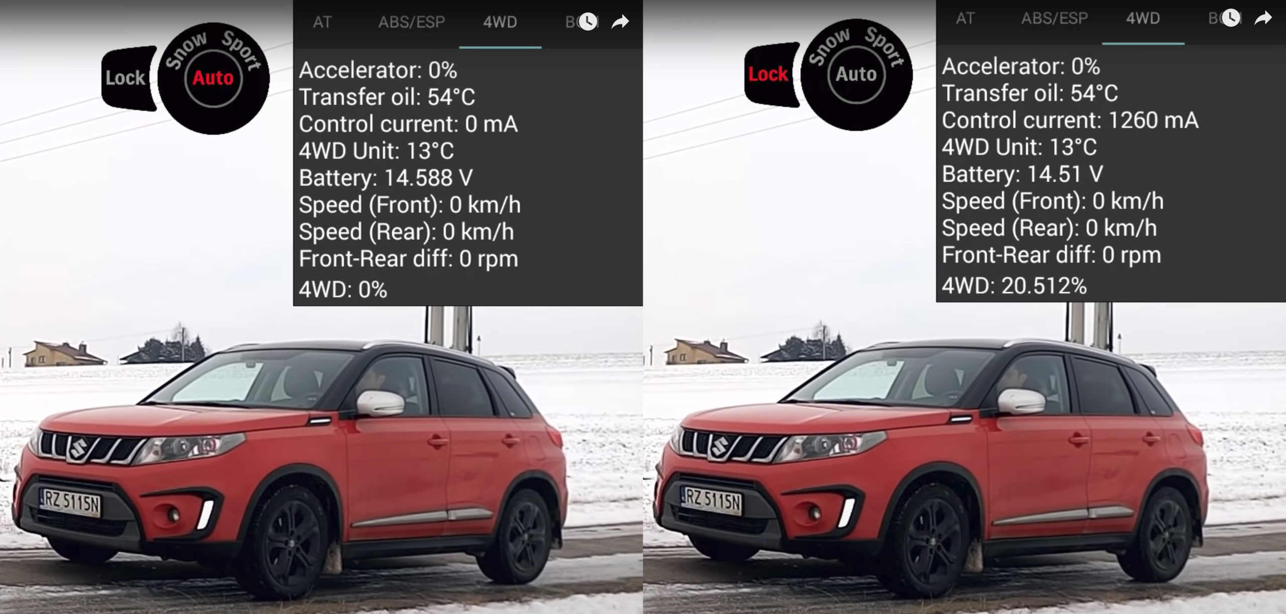
Just take a look at this great video from mine and your favourite Polish AWD roller testing YouTube channel, 4×4 tests on rollers – duszaniespokojna.
Here, the YouTubers helpfully put real-time data from the AWD control module up on the screen for a Suzuki test. You can see at 1:26 in “auto” mode that there is no current to the coupler with no throttle input and the AWD status shows at 0%. When you add throttle and there is a difference in axle speeds, the current ramps up and AWD is applied, but you can see the front wheels slipping before rear wheel action happens.
Next, at 1:45, the driver engages the “lock” button, and immediately, even with the throttle at 0%, there is a fixed current to the clutch-based coupling. As a result, when the throttle is applied, very little wheel slip happens before the rear axle kicks in. In either case, the current to the coupling and locking effect is still variable and feedback dependent. In other words, not locked, but it increases the effectiveness of the AWD system.
For the most part, drive modes have replaced lock buttons. The Honda Ridgeline and RAV4, for example, used to feature lock buttons but have abandoned them in the current generation in favour of drive modes. Put another way, the lock button is just another way to access a drive mode.
Twin-Clutch
Twin clutch systems aren’t a unique AWD system, per-se, rather interesting takes on PTU/RDM setups and worth discussing on their own for a little while.
When we started talking about AWD systems, many words ago, we started with only two differentials (front and rear) then added a 3rd (front, centre, and rear), and then dropped back down to two (front and the rear one within the RDM) and then, with twin-clutch, there was one.
With single-clutch RDM systems, you are still reliant on a rear differential with all its faults for side-to-side speed and torque bias. A solution to the common open differential is the limited-slip differential, but that is costly and still doesn’t allow for active management without further costs and weight. For example, Jeep removed the front active differential option on the Grand Cherokee with Quadra-Drive II with the introduction of the WK II. The idea was that traction control offered most of the benefits without the added expense.
But what if you could get rid of the side-to-side differential entirely?
If you removed the centre coupling and replaced it with 2 couplings, one on either side of a spool in place of a rear differential, then you would be able to control rear axle engagement the same way as before, by binding and releasing the clutches. However, by making each clutch independently controllable, you can also control the side-to-side engagement as well.
With this arrangement, you can simultaneously control front-to-back speed and torque bias as well as side-to-side speed and torque bias by increasing the clutch pressures together or separately allowing differential action through precision programming.
As you might guess, programming is the key. If you need rear axle torque bias and centre differential action, the computer has to balance those needs. To do that it can look at the steering wheel angle, the engine load commanded, wheel speeds, and differences in wheel speeds. From there it can make a calculation with known variables about how much rear axle torque you should need and how much slip it should take on the inside clutch to negotiate the corner based on torque lookup tables and geometric calculations.
The clutches then apply the exact pressure that should be required to each side to make the turn and maintain traction. Less pressure on the slower inside wheel, more pressure on the outside faster wheel. If everything goes to plan, you will never notice. If your inside wheel sensors do sense slip, or the accelerometers show an actual acceleration or yaw rate that doesn’t match up with the maths, the system recalculates in a fraction of a second and commands more torque. In this way, you get exactly the amount of speed bias you need while maintaining torque flow to the inside and outside wheels.
This is torque vectoring, though to be clear, anything with a differential and TBR of greater than 1:1, is technically torque vectoring. Some systems can actually overspeed a wheel providing power vectoring, such as certain Acura SH-AWD versions, but that’s a story for another time. If you have questions on how that works, or any other AWD systems I didn’t mention specifically, be sure to ask me in the comments.
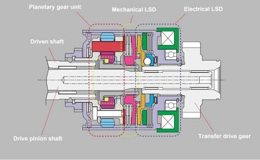
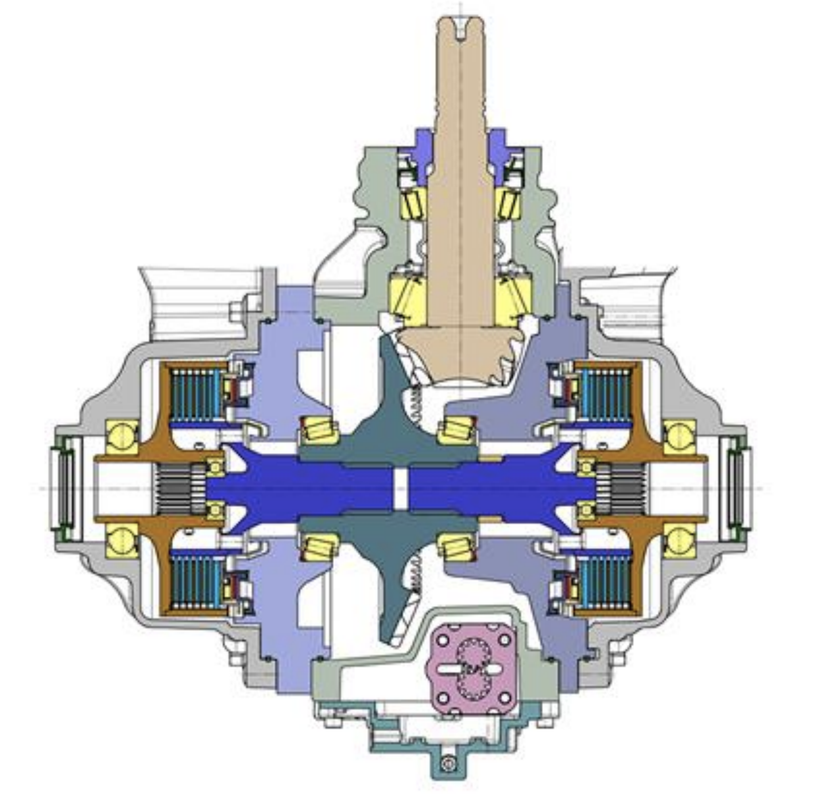
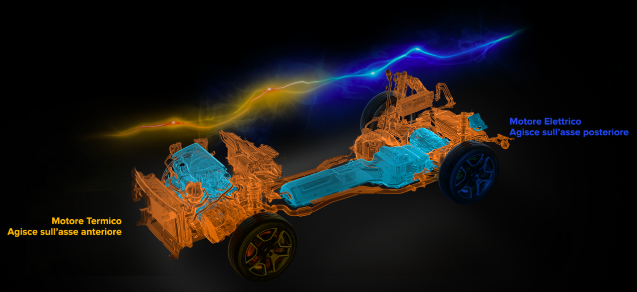
On-Demand Independently Powered Variable-Torque Active (Electrified)
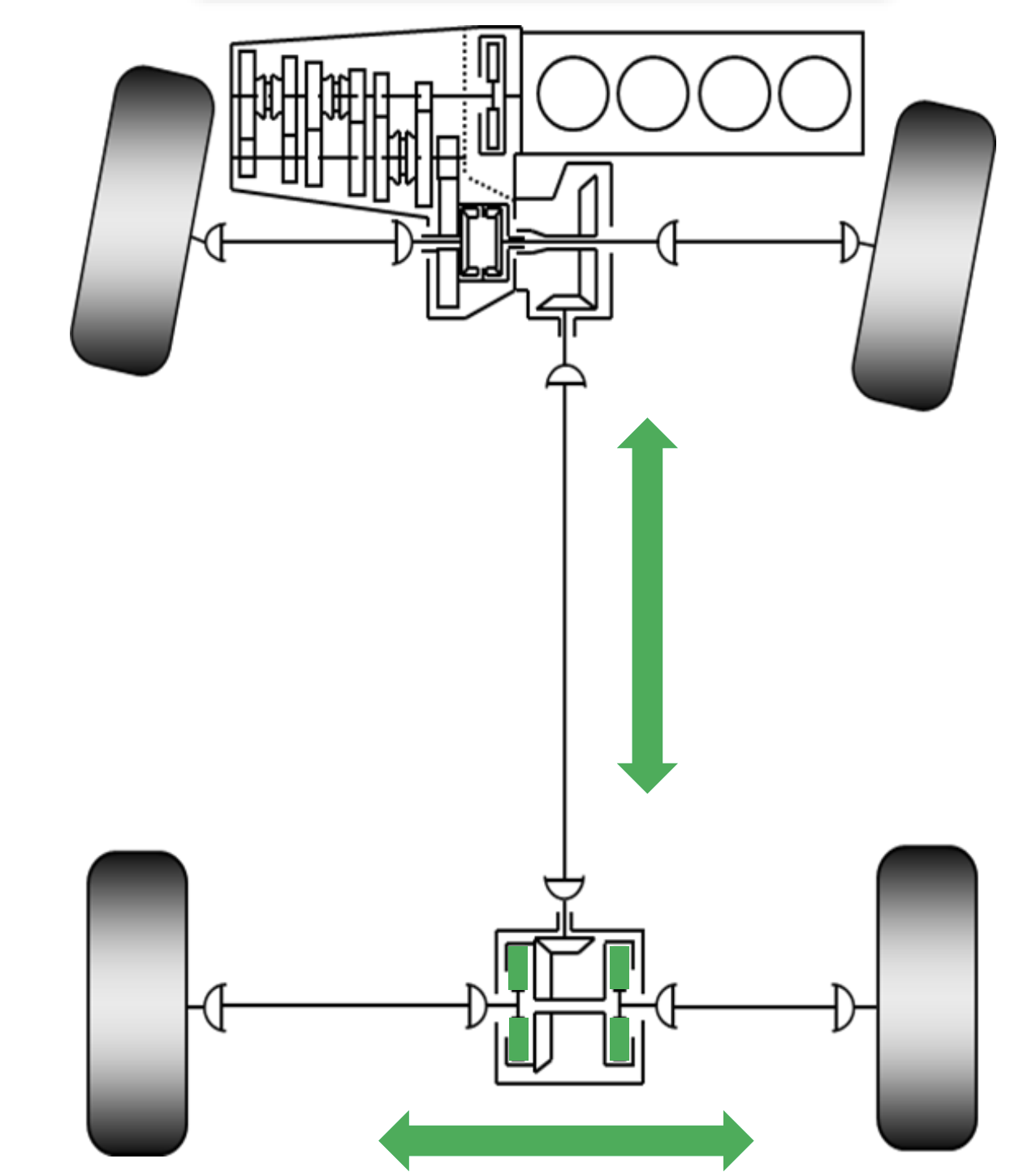
Many hybrid and electrified vehicle all-wheel drive systems are fully independent, completely decoupled drive units complete with their own motors, gearing, and differentials. Power is provided by a battery and supplied to this drive module without ever being physically connected to the primary engine at all. Take for example the AWD Jeep Renegade E. You can see in the graphic there is no physical connection from the front ICE power to the rear EV power.
These are a boon to automakers that already have electrification in their portfolio or are moving in that direction, which at this point is nearly all of them. As you might expect, companies like Toyota are well-positioned for this and have offered an AWD-e system in the US since the 2005 Highlander hybrid. Toyota calls these units MGR, for Motor Generator Rear as they contain a motor-generator in a single unit. Today MGRs are available on many Toyota models like the Camry, Avalon, RAV4, Highlander, Venza, and Prius, and Sienna. Obviously, Toyota doesn’t have this market cornered and other makes and models also have these such as the Volvo XC90 plug-in hybrid and the Pacifica Plug-in hybrid.
Want a deep dive? John’s got you covered. YouTube. Legend.
There are three basic modes of operation for Toyota’s MGR’s:
- Constant torque. In this mode, the current is sent to the MGR based on events and regardless of feedback from sensors. Such as the case with starting from a stop.
- Demand torque. This is when the computer would command additional current based on predictive or reactive external signals.
- Regeneration. During regen, The motor is used to generate electricity and recover waste energy from braking.
Like I said earlier, these are fully electric drivetrains and can actually act independently as a full EV drivetrain in some cases.
These systems are highly beneficial hang on systems for a variety of reasons:
- Full electronic control of secondary axle torque and speed.
- All-weather traction as needed
- Regeneration
- Easily adaptable to hybrid architectures
- Very low drag loss
- Easy way to add total system power
Now for the downsides. Since these are fully independent of the front power unit, you can’t bias torque from your primary power source through mechanical means, and you are limited by the physical properties of your secondary axle power source. What this means is that it’s possible that your secondary axle will provide far less torque than if it were mechanically linked.
For example, a RAV4 prime has 302 system HP but only 54 of those come from the rear axle. While gear reduction does bring that up to about 1355 Nm, that’s still roughly 272 kg-ft less torque than a standard RAV4 AWD can send to the rear axle. In addition, the MGR needs to be geared aggressively to achieve that torque, which means that the electric motor will redline and bow out above certain vehicle speeds providing no AWD benefit at all.
The off-road reviews of these systems aren’t flattering, but they aren’t meant for that. Toyota even says as much in its user manual for the first-gen highlander hybrid. In the “Off-Road driving precautions” section it simply says, “Your vehicle is not designed to be driven off−road.” That’s not to say that these couldn’t be powerful AWD systems, but most manufacturers consider them bad weather traction adders only.
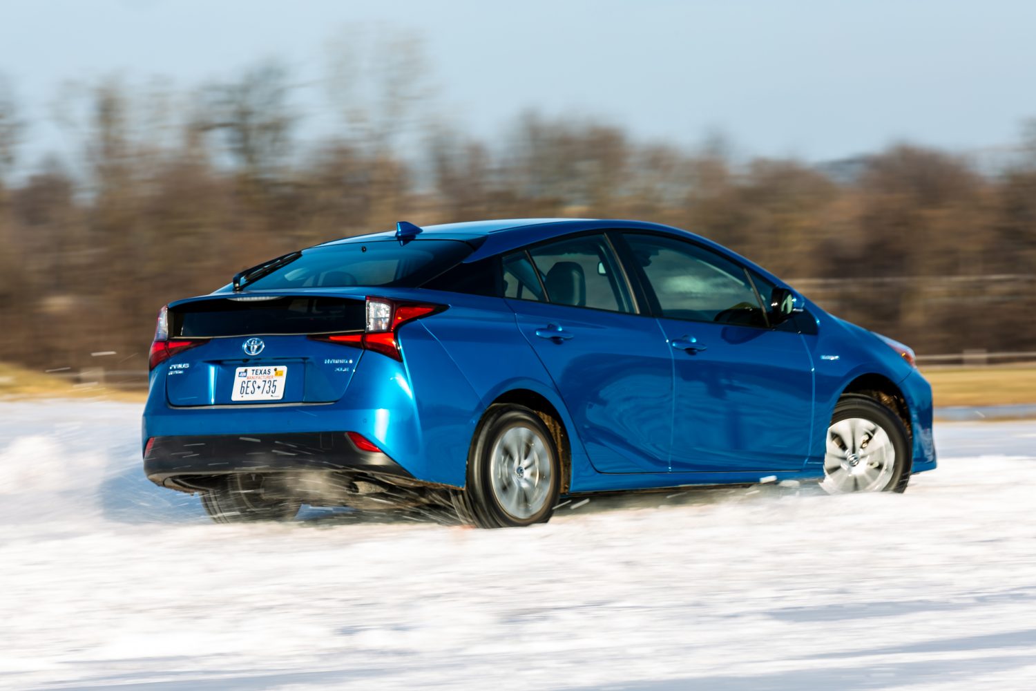
An extreme example would be the optional AWD-e on the Toyota Prius, which contributes a whopping 5 KW to the total, or about as much as a shove from a few strong friends. Still, when you are stuck in the snow, a shove from a few strong friends is sometimes all you need.
As far as side-to-side action, these typically used open differentials, but there is nothing to stop manufacturers from using traditional or active LSD’s, twin-clutch setups, or even dual motor.
These same principles apply to more off-road focused EV systems like Rivian or the new GMC HUMMER as well, whether they are dual motor or quad motor.
So that’s it for now. That’s how AWD systems are categorised and how they work. Simple right? Look, if you got to the bottom here you are to be commended; thanks for sticking with me.
Thanks again to David Tracy, Professor John Kelly, Chip Fairbanks as well as Rick Barnes from JTEKT Torsen North America for offering their expertise and hospitality.